In Electronics Production, a key part of most technolgies is a Printed Circuit Board (PCB). PCBs are defined as custom etched/printed boards.
Electronic components (such as LEDs, resistors etc.) are mounted onto the board to form a working circuit or assembly.
PCBs are essential for most common technology available in the market and are way better compared to the standard breadboard.
So why choose PCBs over breadboards? Some reasons include:
- customized electronics for product requirements
- customized footprint (e.g. occupies less space)
- more reliable (soldered PCBs last longer than wired breadboards)
- can prototype and iterate faster
- better product integration
With that, how are PCBs made? There are 2 ways to do it.
First method is through etching. Etching uses certain chemicals to etch out the outlines of your PCB. There are many types of chemicals
used for etching, however all require waste control in order to dispose of due to their chemical disposition.
Therefore, in the Fablab, this method is not used.
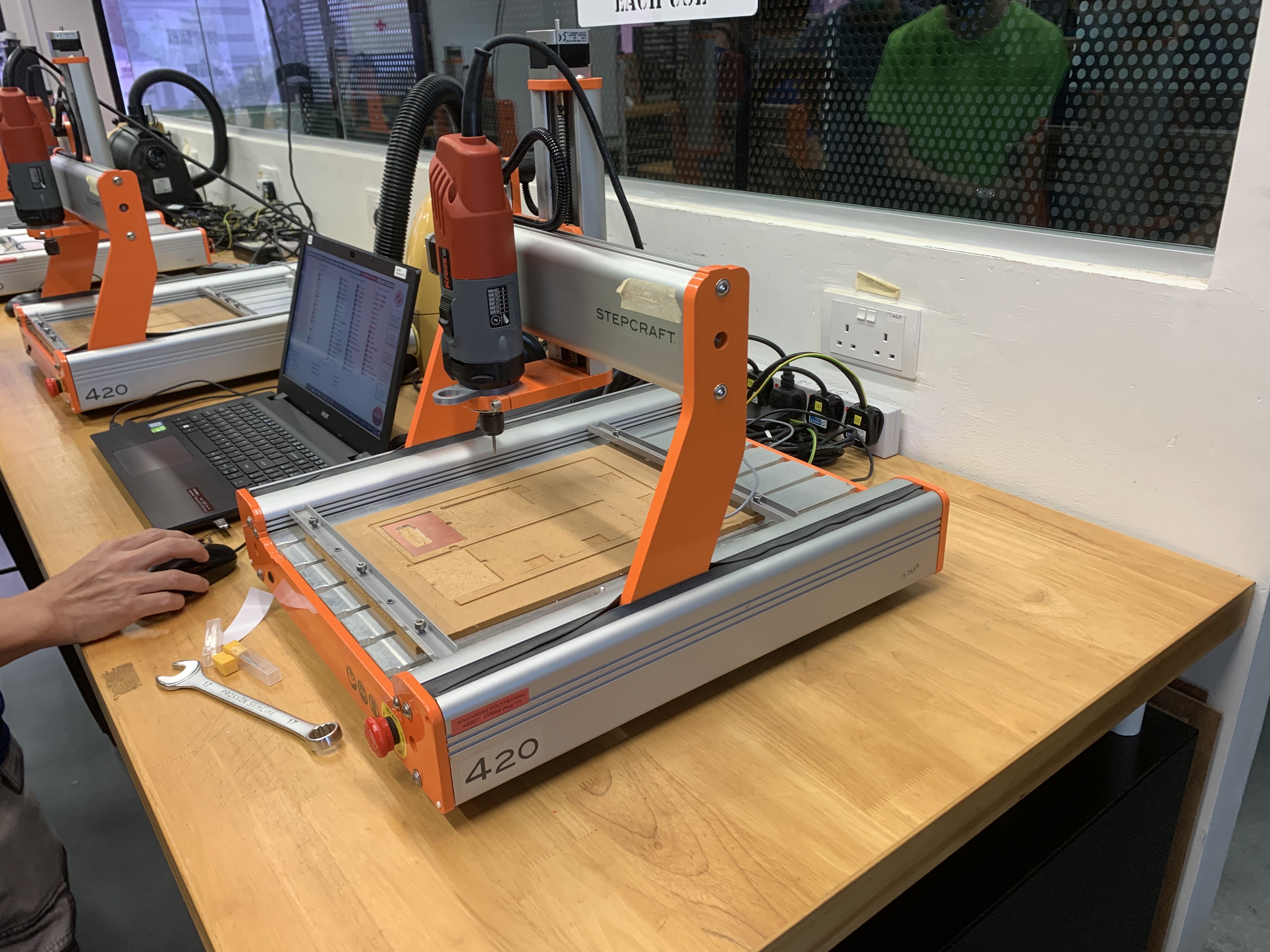
The second method is to mill out your PCB. Using a small CNC machine, the traces can be milled out and the PCB can be cut out.
Compared to etching, this method is much simpler and is used in the Fablab.
In the Fablab, the Stepcraft 420 machine is used, paired alongside UCCNC post processing software.
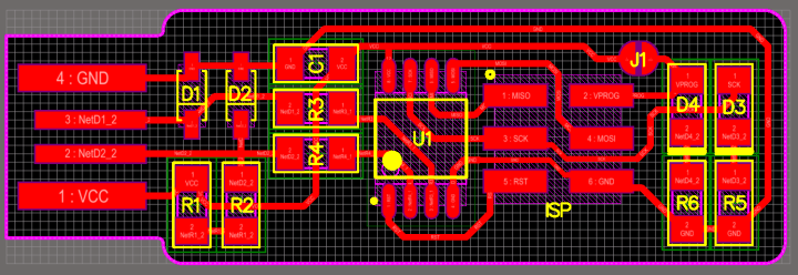
For my assignment, I was tasked to mill out my own ISP programmer.
An ISP programmer is an In System Programmer used to program certain microcontrollers.
To create my ISP, I will need to first generate the g-code for both the traces (connections) and the outline (cut out pcb)
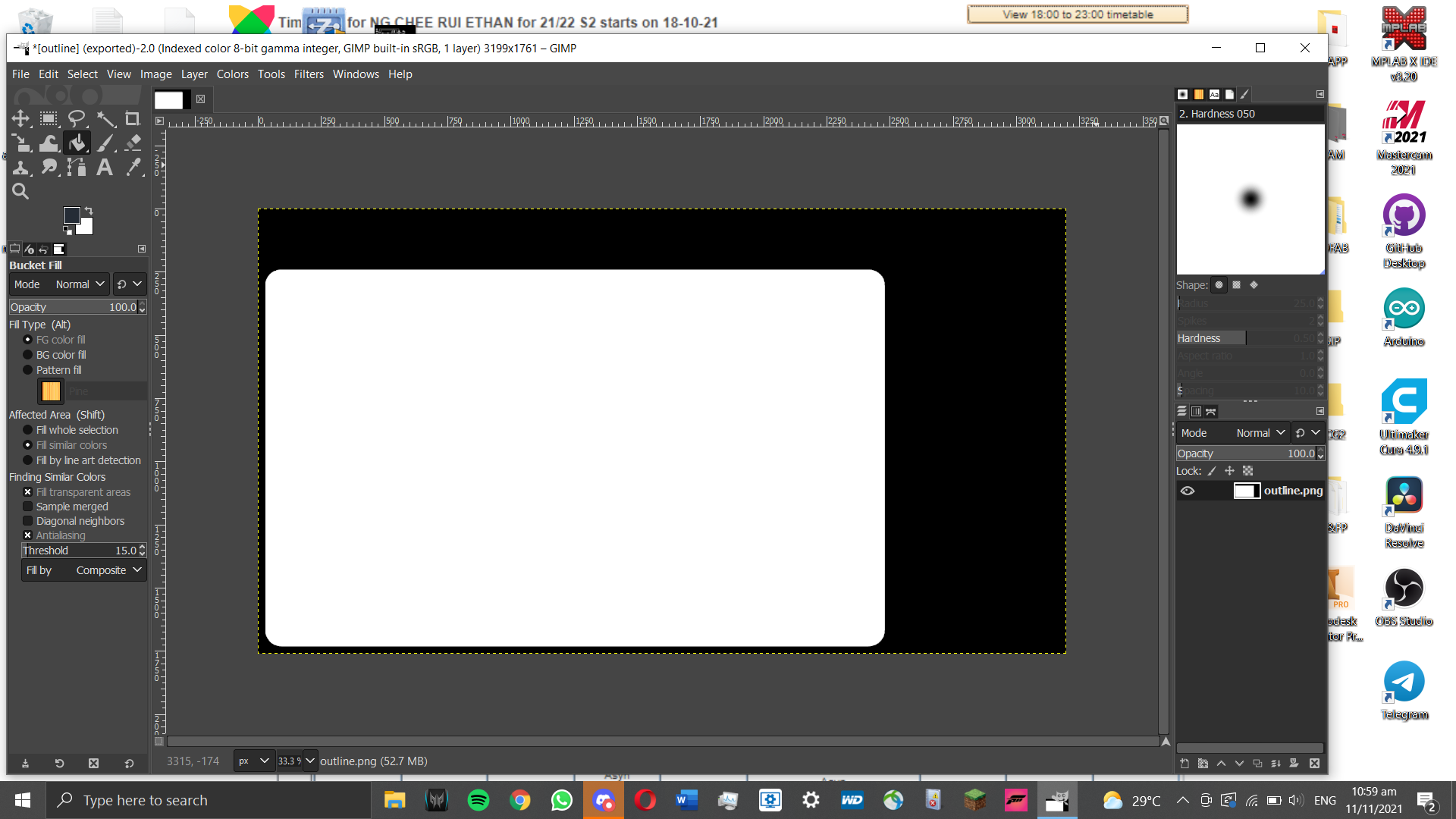
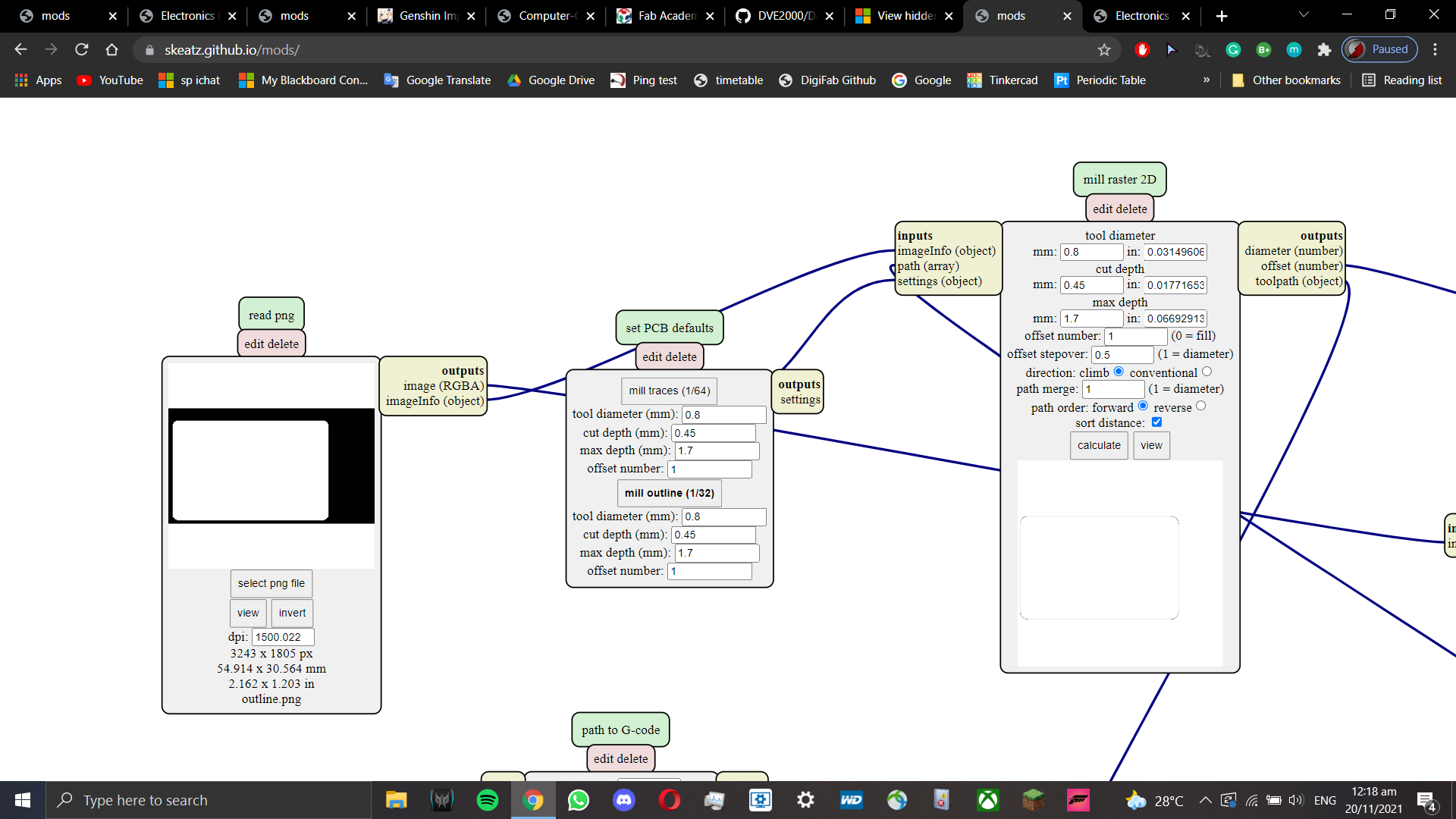
Using Mods, this is how the g-code is generated.
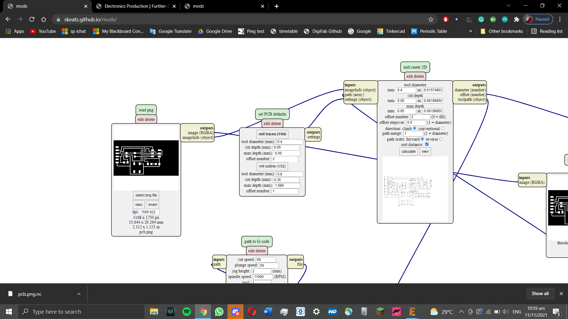
Once the right program is loaded, we have to change the settings to suit our needs.
Note that these settings are not always needed and can change depending on your needs.
For traces, the endmill size is 0.4mm, cut speed around 60mm/min, cut depth 0.05mm, total depth 0.05mm, offset 3
For outlines, endmill size 0.8mm, cut speed 70mm/min, cut depth 0.45mm, total depth 1.7mm, offset 1
Press calculate and save the g-code. Now, we can start milling our PCB.
Loading up the g-code in UCCNC post-processor, before I can start milling, I need to check a few things.
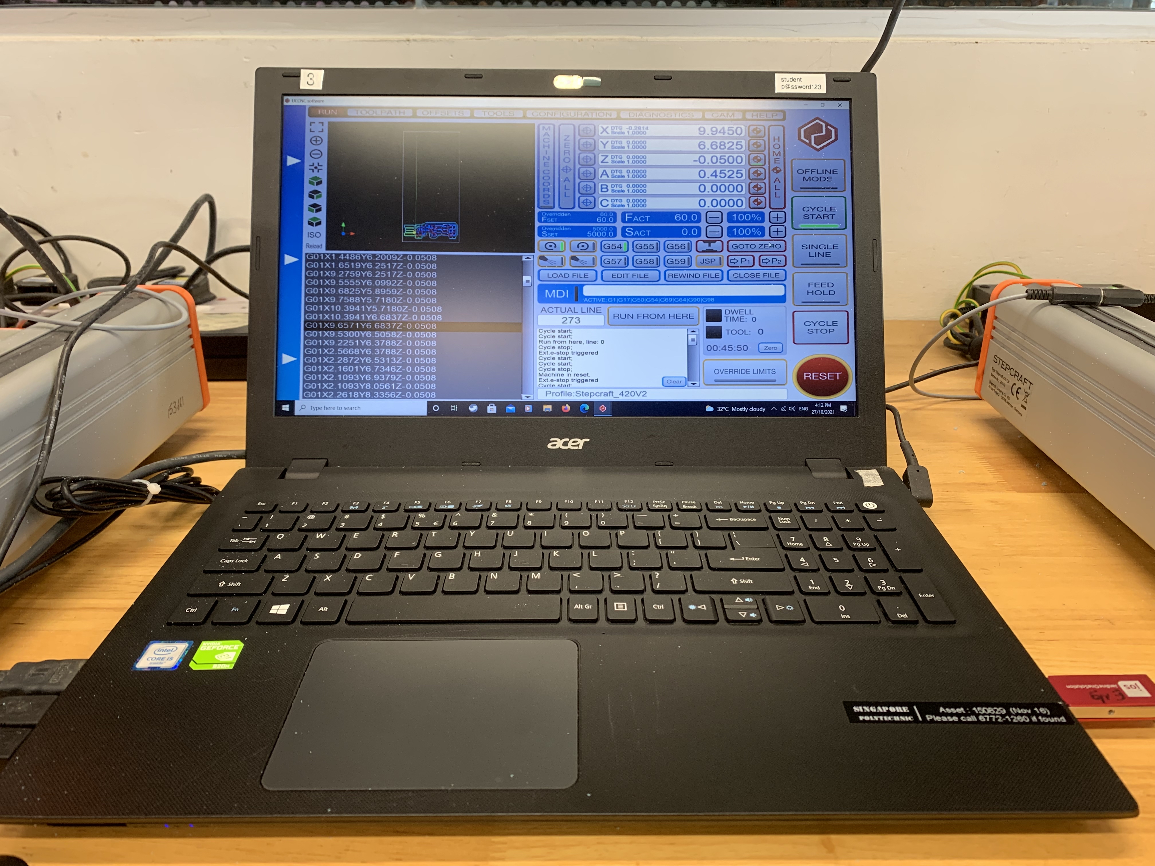
First is to ensure the copper board used is stuck at a flat surface. It must not move while milling.
Afterwards, we attach our endmill. Start with the traces, then cut the outline out.
Next, we have to calibrate our axes. Calibrating the x and y-axes are simple. Find the origin point (bottom left) of your
imported g-code and set a point as your origin. After that is done, setting the z-axis needs a bit more work.
Stepcraft 420 comes with a probe that you use to set your z as 0.
By placing it under the endmill, we can use it to set our z as 0.
Once that is done, we can start milling.
Here is the ISP milled out. I got really lucky with the endmill as it was sharp. The board barely had any burrs.
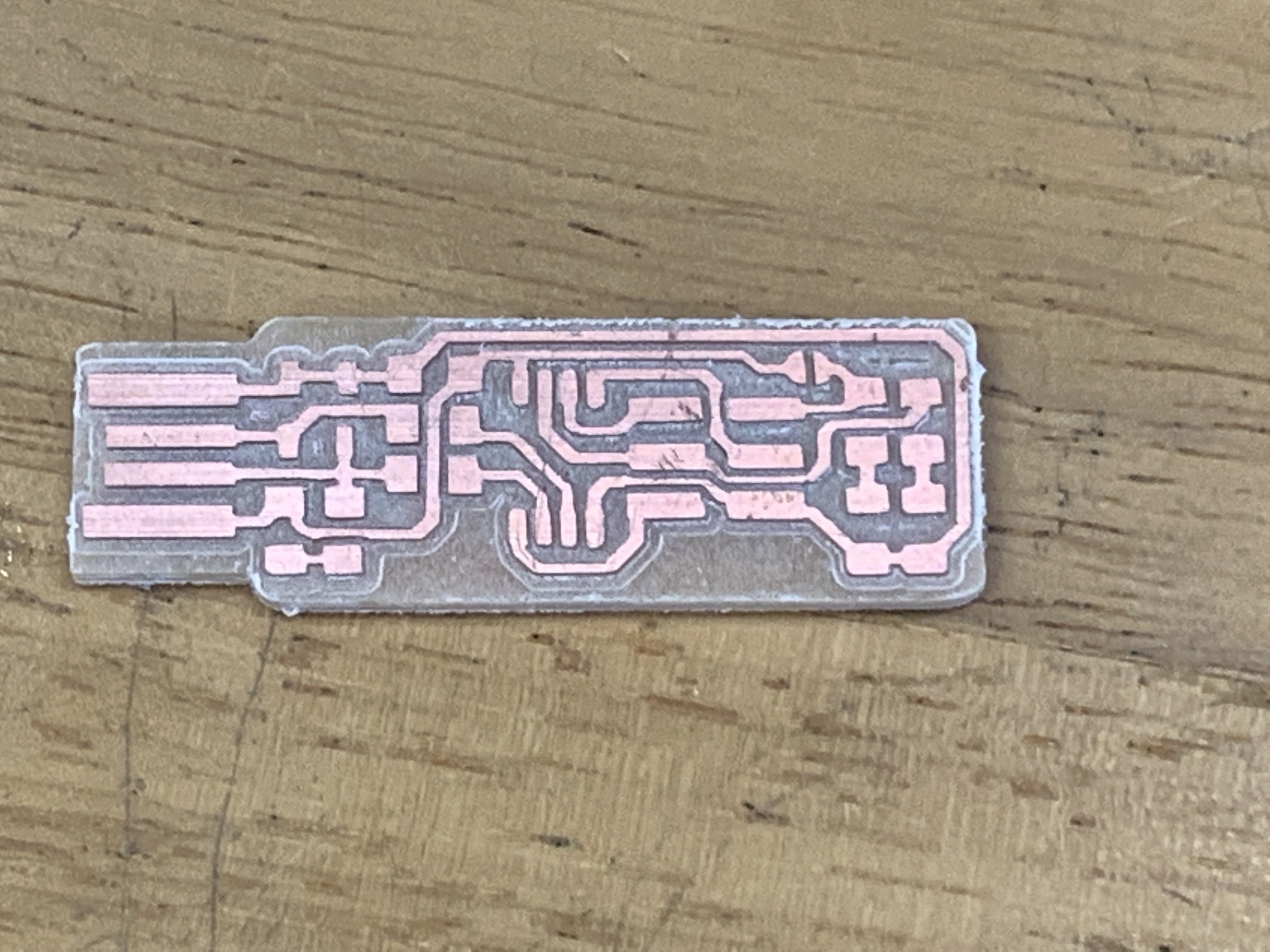
This step is optional, however to reduce the chances of shorting your PCB you can remove dead copper
(copper that does not contribute to any electrical connections in your PCB).
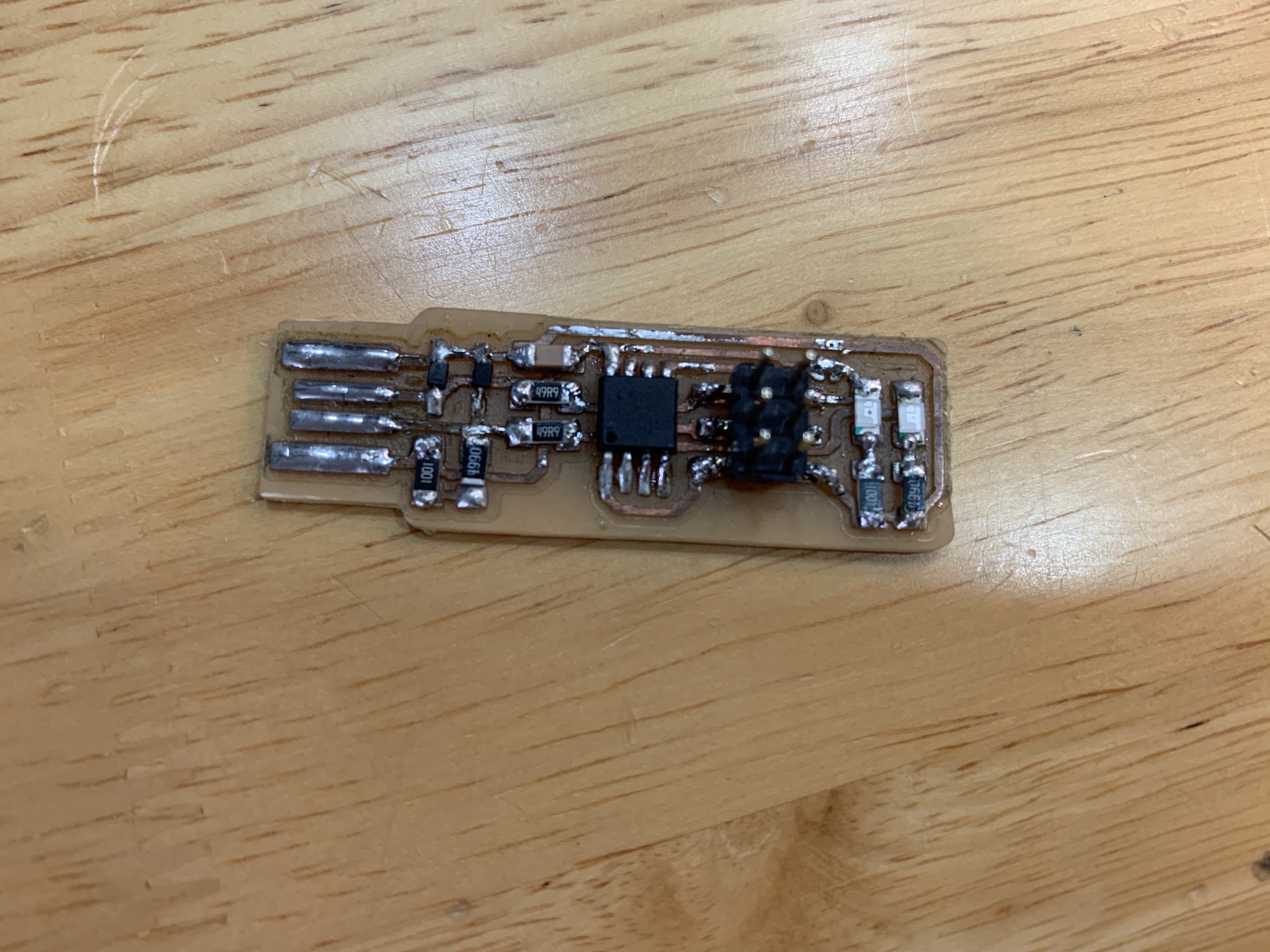
With our ISP milled out, we need to assemble the electronics.
For our PCB, our electronic components are SMD (surface mounted devices). They are much smaller than your average component,
but they serve the same purpose. For most modern electronics, SMDs are better for more compact PCBs.
The components we need are:
- ATtiny45/85 X1
- 1KΩ resistors X2
- 499Ω resistors X2
- 49Ω resistors X2
- 3.3V zener diodes X2
- red LED X1
- green LED X2
- 100nF non-polar capacitor X1
- 2X3 pin header X1
Below is the PCB with the soldered components.
With the hardware done, it is time to program it.
To program it, the following software has to be installed:
- Atmel GNU Toolchain
- GNU Make
- avrdude
- USB Driver (Zadig)
After that, we need to update the path for these software installed. (Windows > Advanced System Settings > Environment Variables)
These have to be added in:
- C:\Program Files\avr8-gnu-toolchain\bin
- C:\Program Files (x86)\GnuWin32\bin
- C:\Program Files\avrdude
Once the installations is done, some modifications need to be done.
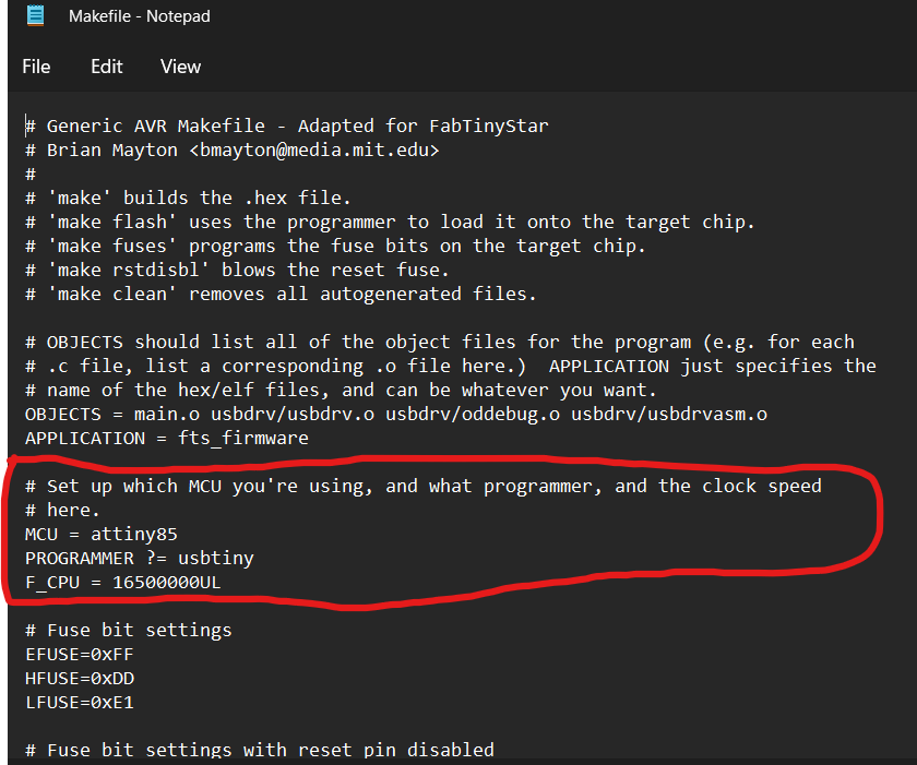
First is to configure the makefile. Update MCU to whatever microcontroller you use (attiny85 for me)
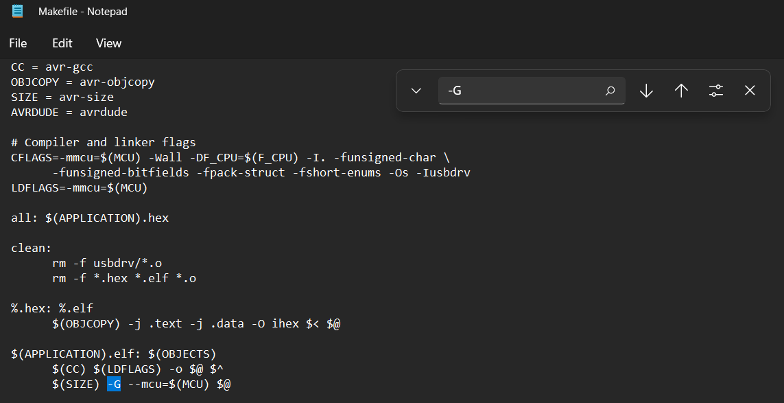
Next, edit the highlighted text so that it shows -G. For some reason I had to change it, otherwise the whole compiler stopped working.
Once done, head to command prompt. We will check to see if our compilers are done right.
First, type make-v and press Enter.
Next, type avr-gcc -version and press Enter.
Finally, type avrdude and press Enter.
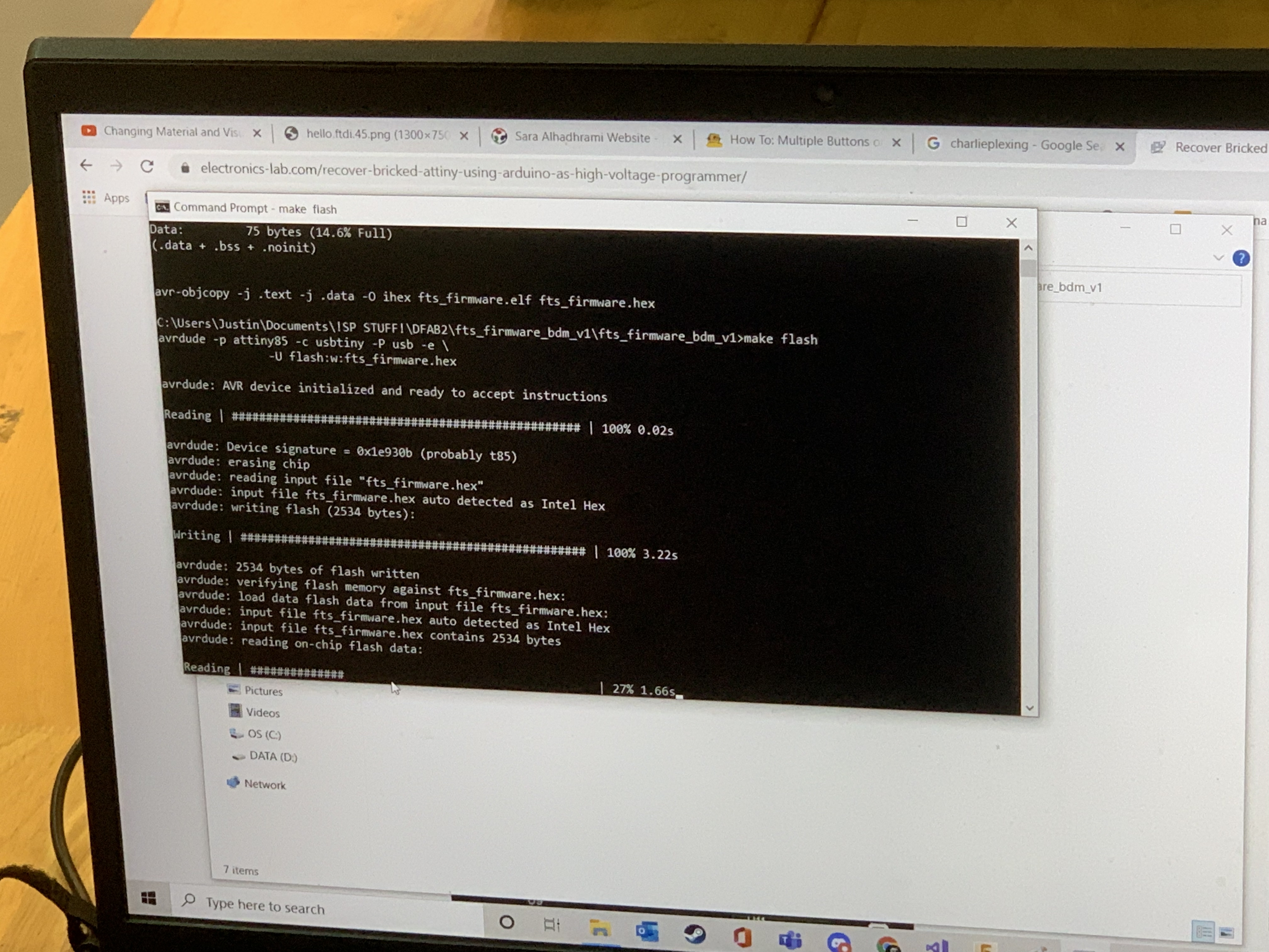
Once the check is complete, we can run our programs to program our ISP.
First, type 'make flash' to upload the firmware to our ISP.
Second, type 'make fuses' to program fuse settings for our ISP.
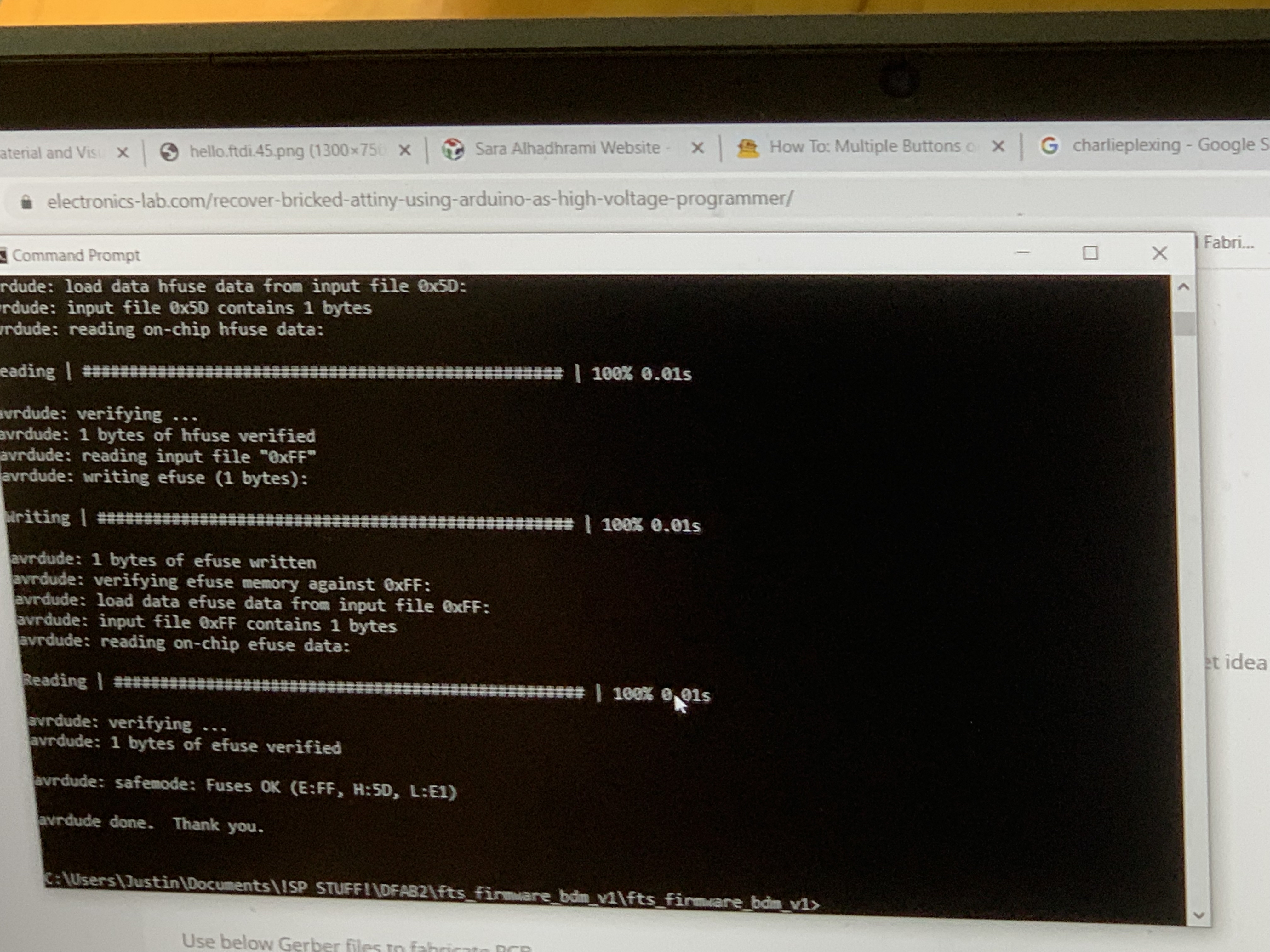
Lastly, type 'make rstdisbl' to disable our reset pin and convert it to a general purpose I/O pin. This makes our ISP programmer not programmable.
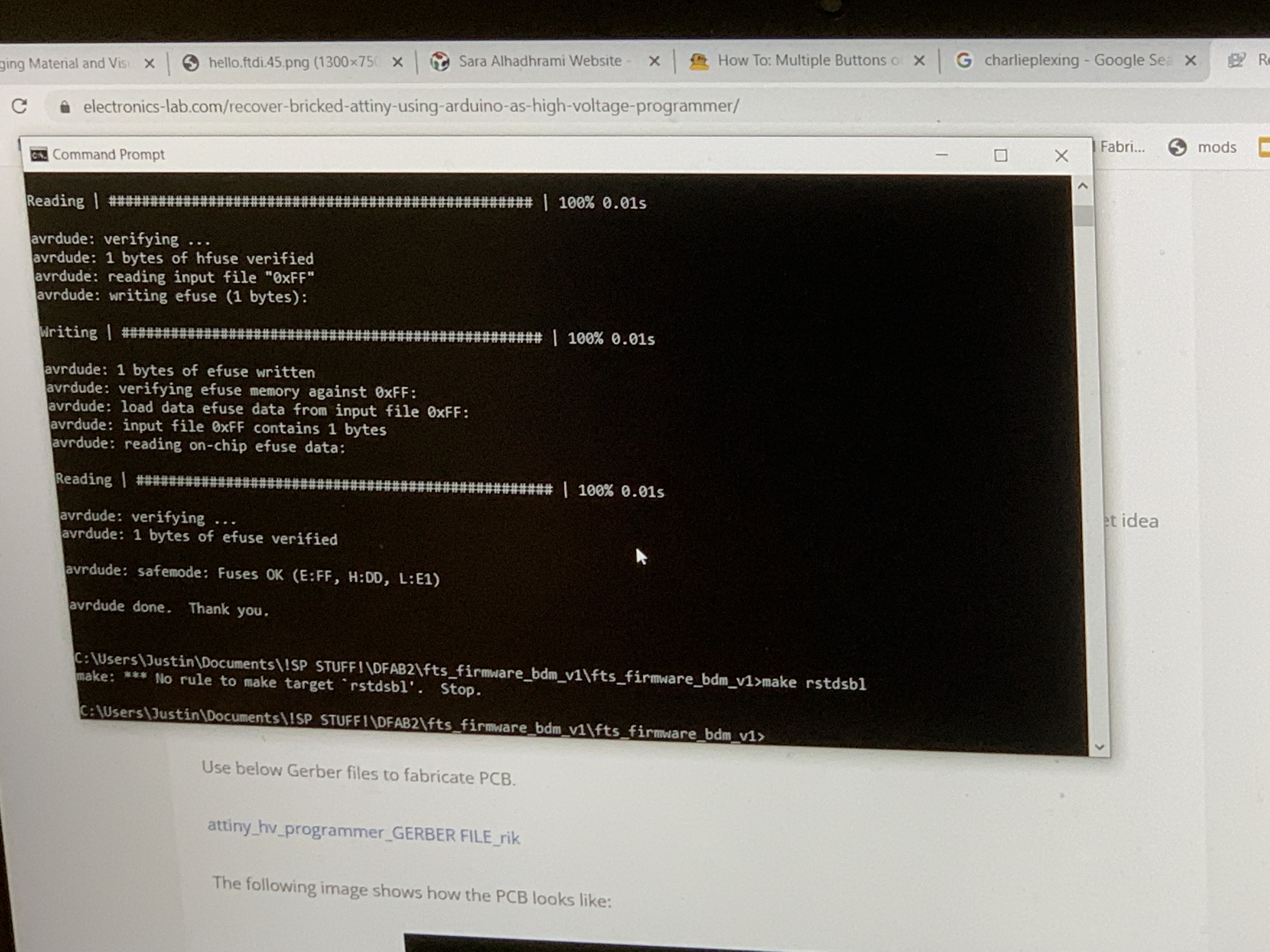
Image credit for the programming goes to Justin as I did my programming on another computer.
With that, my ISP is done.