Embedded Programming (Arduino)
Arduino coding language uses a language similar to C++. The good thing about Arduino is that it combines both software programming
and electronics to make your engineering systems come to life.
Arduino itself uses a software called Arduino IDE for your coding. It is kind of similar to softwares like Visual Studio Code, except it is tailored
to Arduino. There are various libraries to reference from for different electronic components (e.g. stepper.h library for stepper motors). You can think
of them as extensions to your base code. Depending on what you want your electronics and code to do, certain libraries will come in handy.
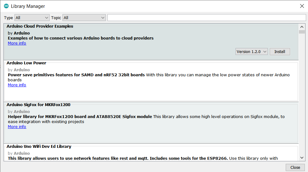
Below is Arduino's own library manager. It is where you can choose certain library files to install and include in your code.
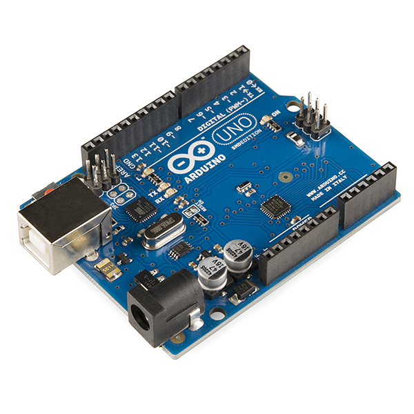
Depending on the complexity of your projects, the type of Arduino board you use will vary. For our case, the Arduino UNO will
be our focus. The Arduino UNO has 12 Digital Output pins, 5 Analog output pins as well as 3.3V/5V/Ground pins for wiring. It has a USB connection
port to upload your code into the Arduino system itself, as well as a power jack for external power sources.
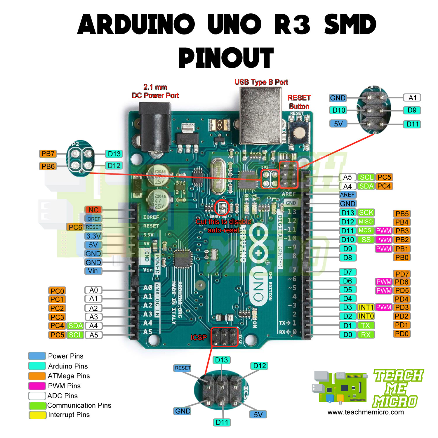
Below is the pinouts for the Arduino UNO.
Image Reference:
In any Arduino programming, a few things are always necessary to include.
One of which is defining input and output pins. Depending on what you want to make, certain electronic components require some connection
to an input or output pin. Note that the input/output pins should align with the hardware wiring, for obvious reasons.
Another thing to include is user-defined functions. In any code, there will be user-defined functions that the code should execute. Usually, a user-defined function consists of 4 parts:
- A reserved word indicating the return data type of the function's return value. (e.g. int, double etc.) If nothing is returned, a "void" function is used.
- Function name.
- Any input data/parameters required by the function. They are contained within parentheses. It can be omitted if no input data is required.
- Function statements enclosed in curly brackets {}.
For wiring and electronics, a free software that I used was TinkerCAD. For what it's worth, it offers the basic introductory electronic simulation experience.
While there are other better softwares to use for electronic simulation such as Multisim, TinkerCAD does its job well. Thus, if you do not have the financial flexibility to purchase an Arduino yourself or get a more advanced electronics simulator, TinkerCAD
would do a decent job as a substitute. One thing that TinkerCAD does well is its integration with Arduino software. It offers both block and text code which are interchangable, which was quite a neat function to use especially for a novice programmer like me.
An assignment given was to create a 555 Timer Circuit using TinkerCAD.
An assignment given was to create a circuit with a 555 Timer IC and simulate it on TinkerCAD.
A 555 Timer IC typically operates as a timer. It has 3 modes of operation: Astable, Bistable and Monostable.
- In Astable mode, the output cycles on and off continuously. It typically does pulse generation.
- In Bistable mode, the trigger and reset pin determine the output of the circuit. It functions as a flip-flop circuit.
- In Monostable mode, it outputs pulses for a set amount of time. 555 Timer ICs operating in this mode tend to serve as timers.
In this circuit below, the 555 Timer is in Astable mode. The output would be a pulsating ON/OFF signal which would cause the LED to flash.