Computer Aided Design
For Computer Aided Design, two assignments were given. One of which was to create a knight chess piece with the following dimensions:
- 30mm base diameter
- 50mm height
- 5mm head thickness
- Hollowed base
- 30mm base diameter
To start off, a reference picture is taken so that we can have something to refer to. It is scaled to meet the requirements stated above.
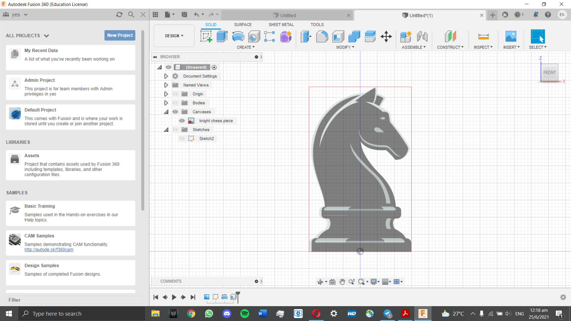
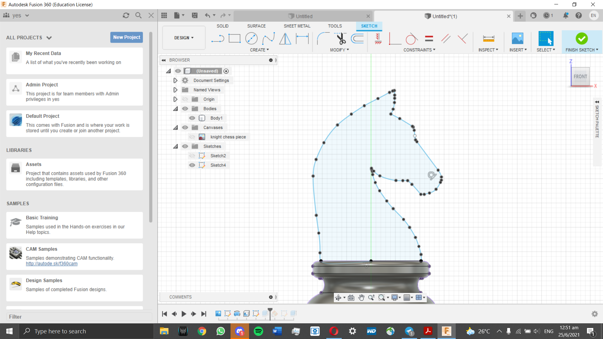
Next, we sketch out the base. Since we are using a reference image, we will be tracing out half the base
using line tools as well as spline curves for curved areas. Due to how we are copying features off a
reference image, the 3D model may not be fully accurate and constrained.
Afterwards, we use the revolve tool to create the base sketch.
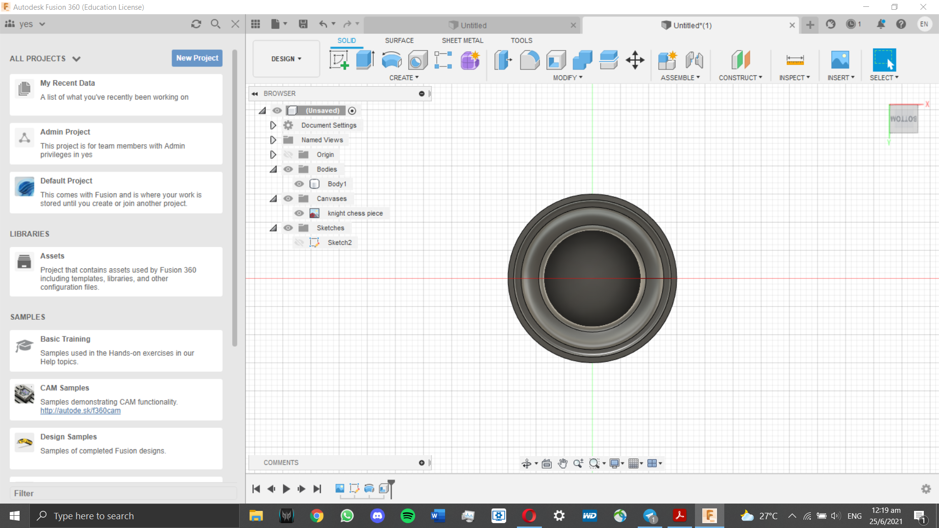
Before we can start with the rest of the knight chess piece, we have to make the base hollow. To do that,
the Shell tool is used. The wall thickness is set to 1mm.
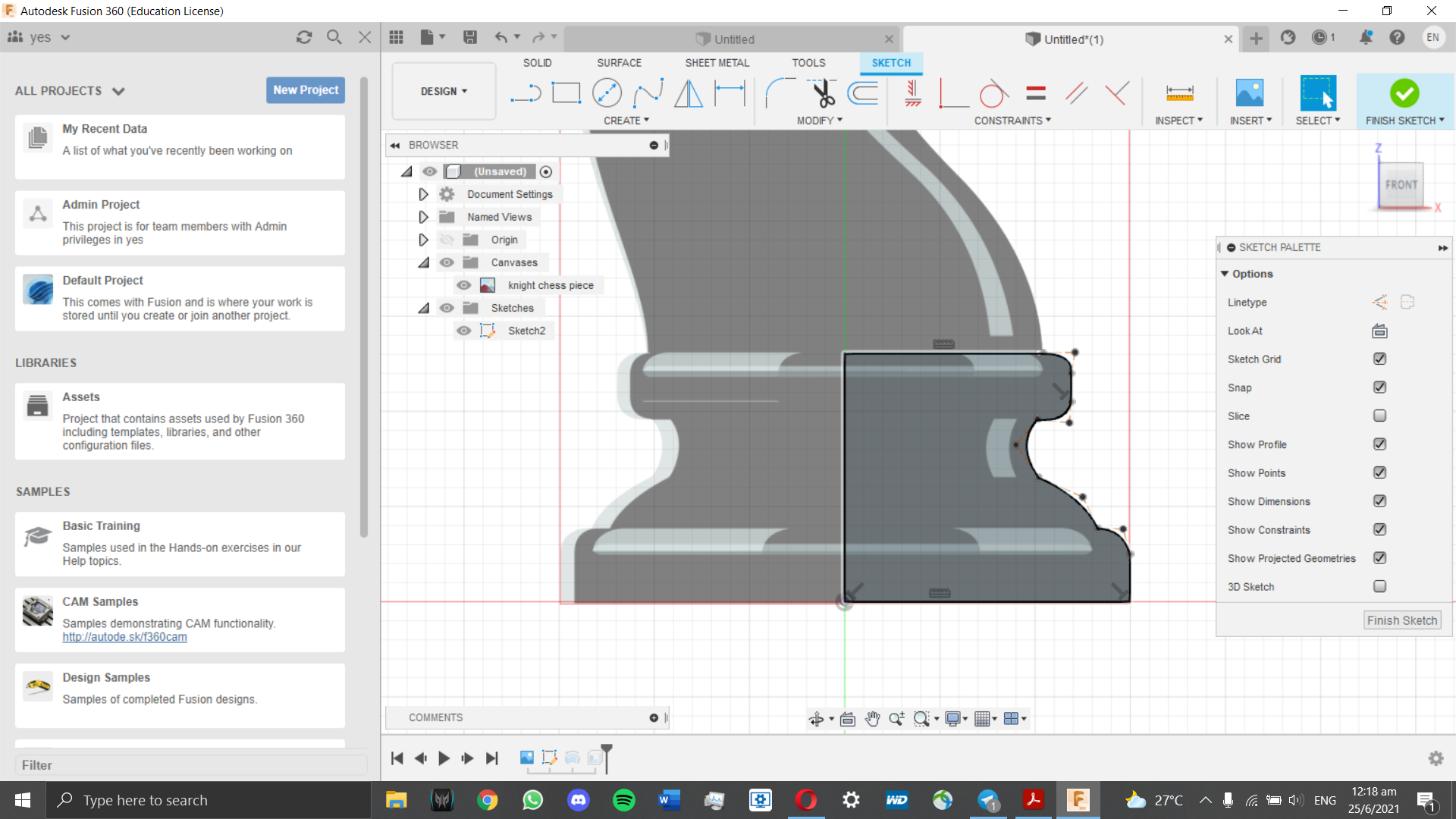
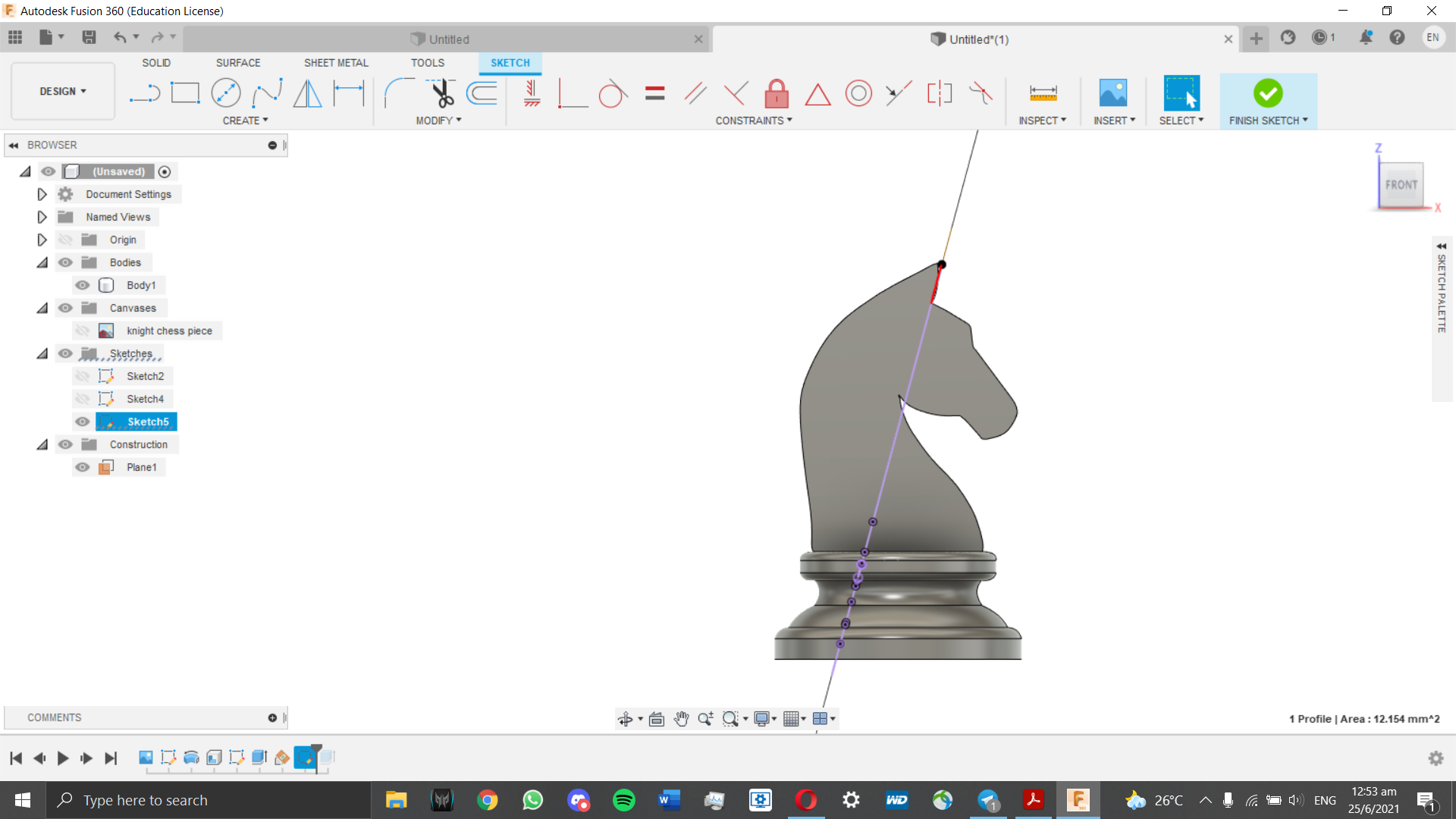
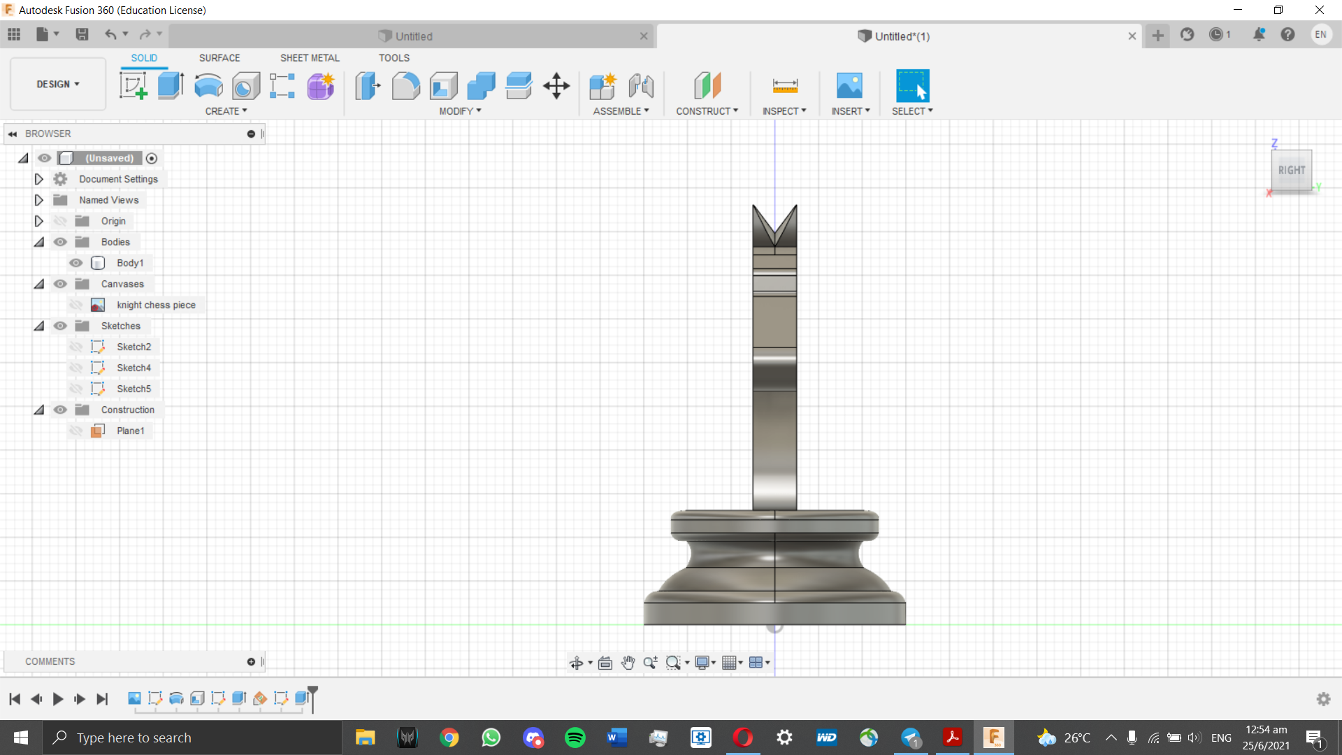
Now that the base is complete, we can move on to modelling the head of the knight chess piece. To do that, we
refer to our reference image and try to trace it to the best of our ability. For this, I used the spline tool to draw
the curves of this sketch. I also had to project the top of the base so that it can be used as a reference point
during the sketch. I decided for simplicity's sake, I would not model the mane.
This would make the 3D printing faster.
The top sketch was extruded to the distance required as stated above (5mm head thickness).
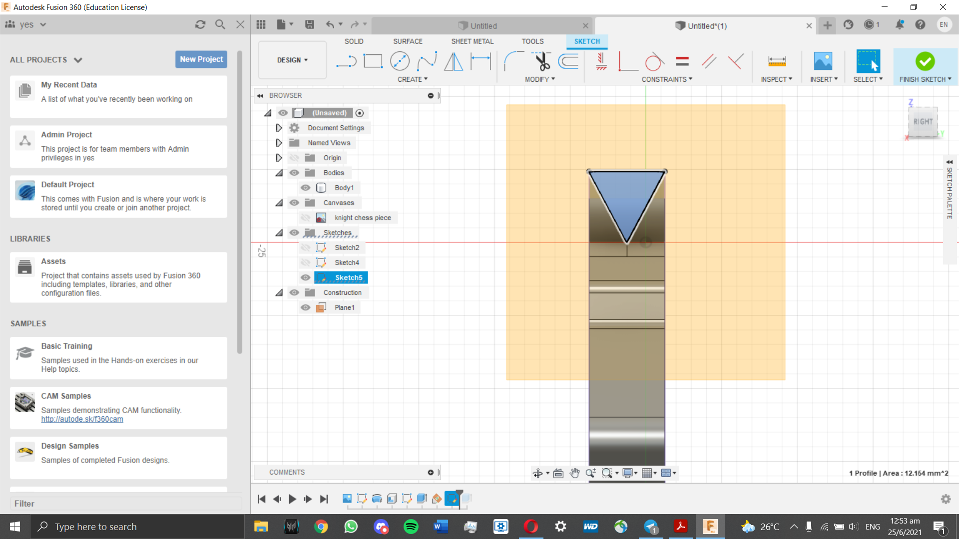
Now, time to do the ears. This is a bit complicated as there is no reference plane to do the sketch on. Thus, I had to
create a new angled sketching plane right where the ears are.
With the sketching plane done, I can make the sketch to carve out ears for the knight chess piece. A triangle will be sketched
and extruded as a "Cut" function instead of a "New Body" function.
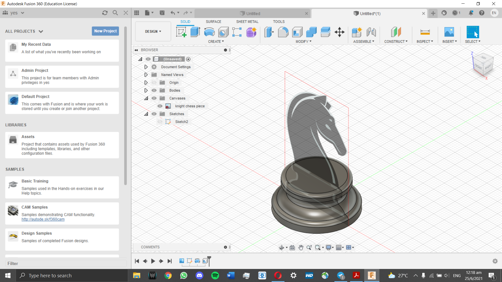
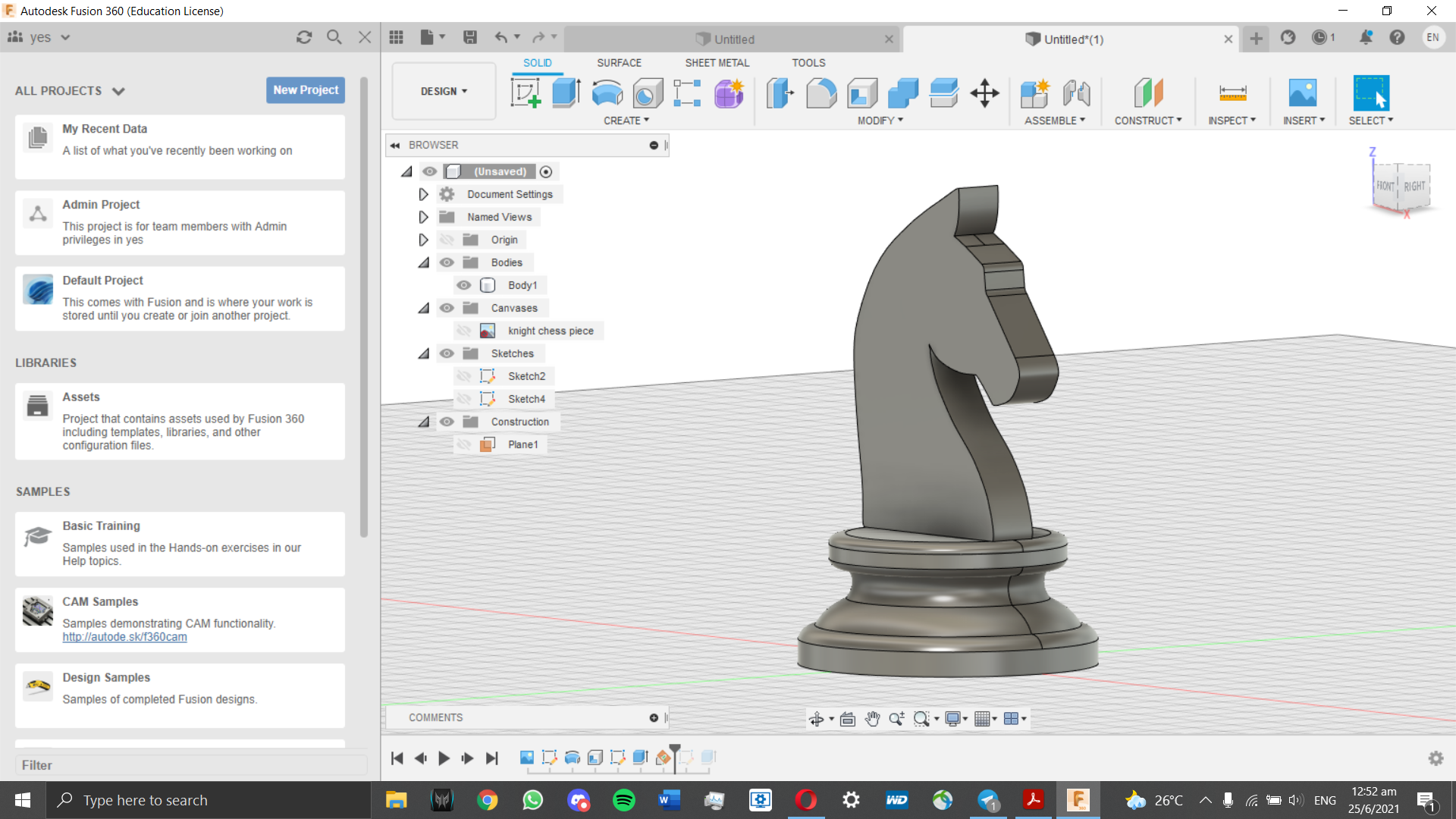
With that, the Knight Chess Piece model is finished. Below is the embedded 3D model itself.
The other assignment was to create a music box with a movable lid with parametrics. Having a parametric design allows it to be
edited seamlessly by changing certain variables instead of editing every single affected part of the 3D model.
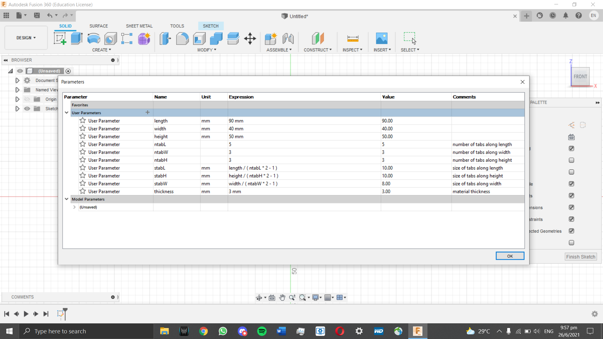
Before we start 3D modelling, we have to set our variables first.
Here are the variables set in this model.
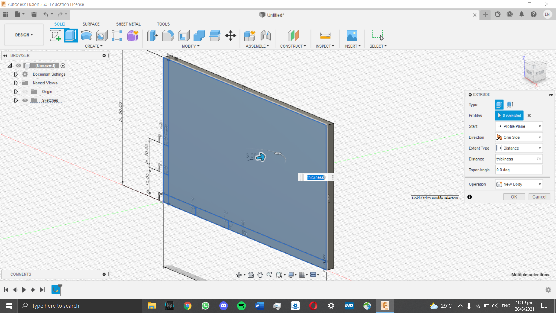
To start off, we must create a basic box (without the lid).
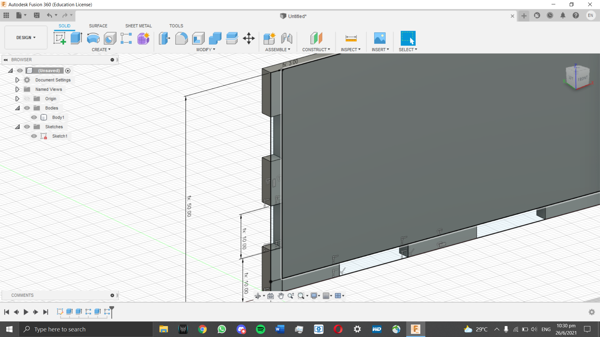
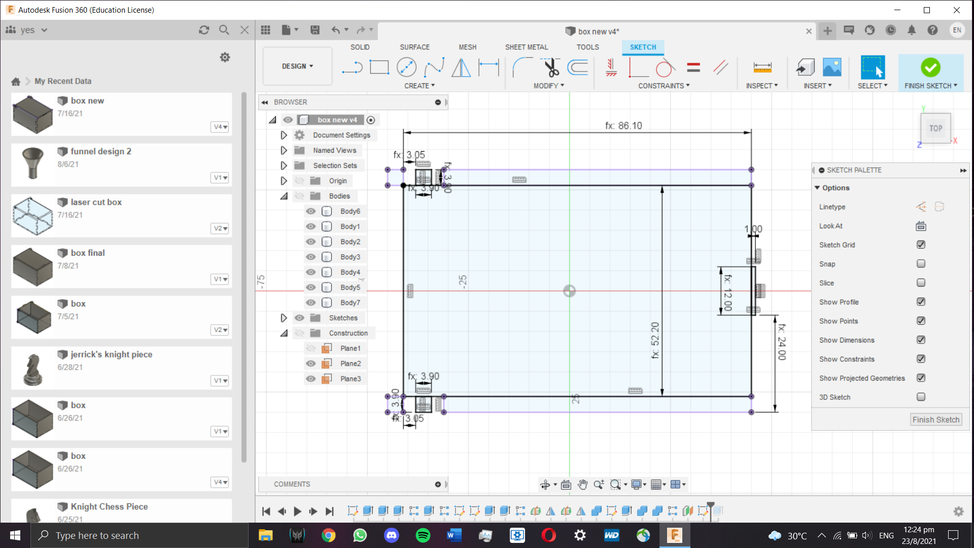
A rectangle was first sketched and dimensioned to the length and height mentioned above. One set of tabs is also sketched and
dimensioned according to our predefined variables. It is then extruded to our set thickness as a "New Body" operation.
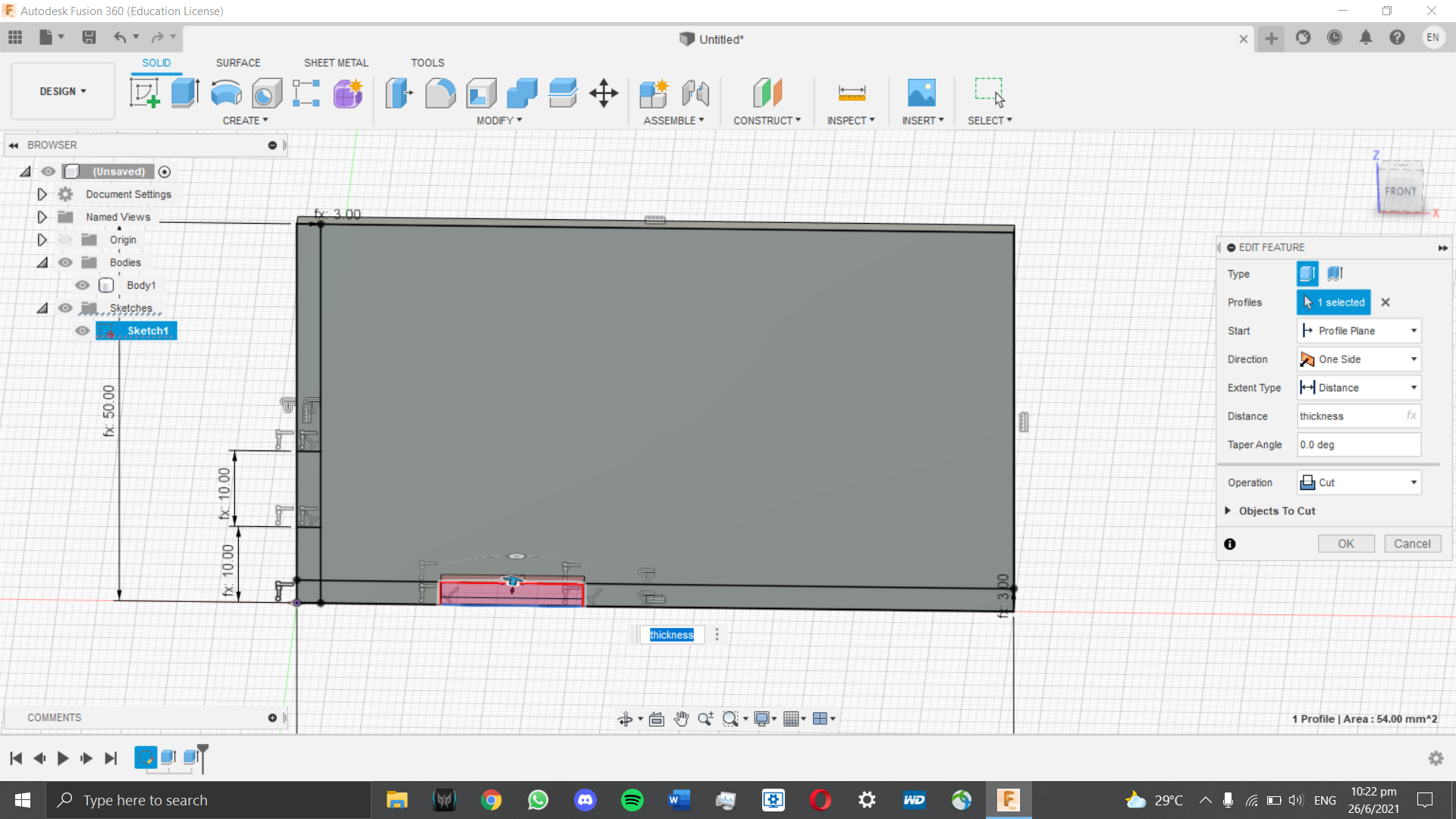
Next, another extrusion is performed, this time as a Cut function to cut away the tabs so that our box can be assembled once laser cut.
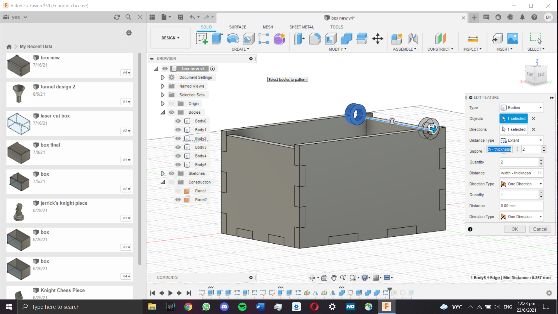
Afterwards, I patterned the tabs twice in two directions, once across the length of the box and along the box height twice (both sides).
Now that one face is done, the side of the box (width) has to be done. The same process as creating the first face is made, except it
is anchored to the front edge of the first tab made. It is dimensioned and constrained via our predefined values, and extruded to our
preset thickness afterwards. The only difference is that the height of this tab is slightly shorter, and there is a reason behind it which will be explained later.
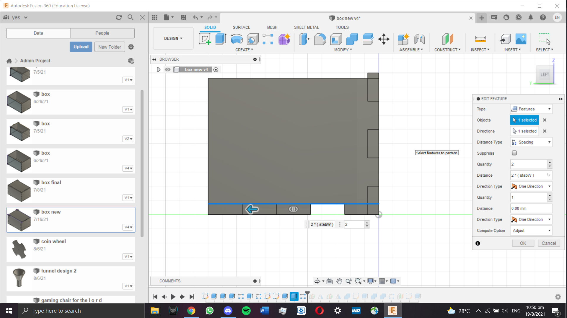
The tab spacing along the width of the box is cut and patterned along the width as shown below.
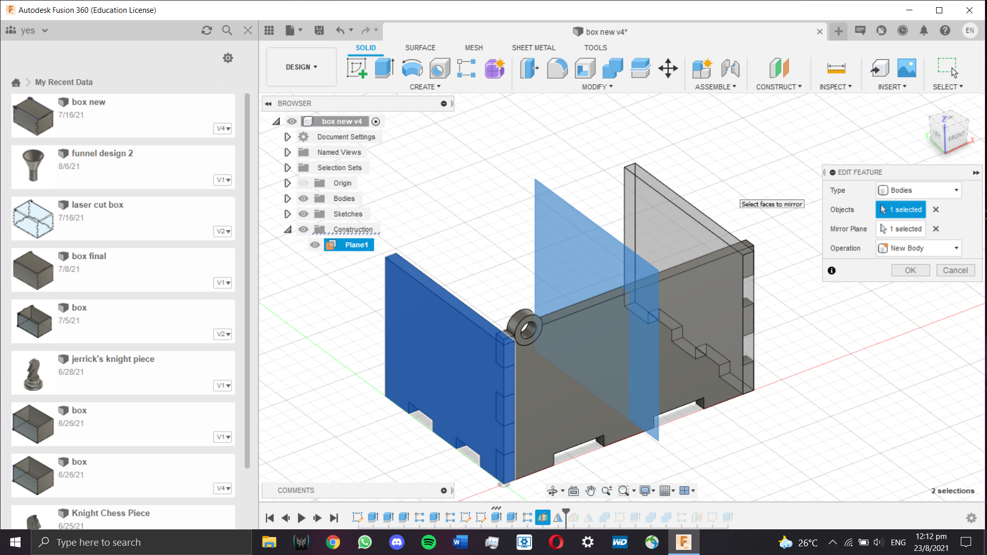
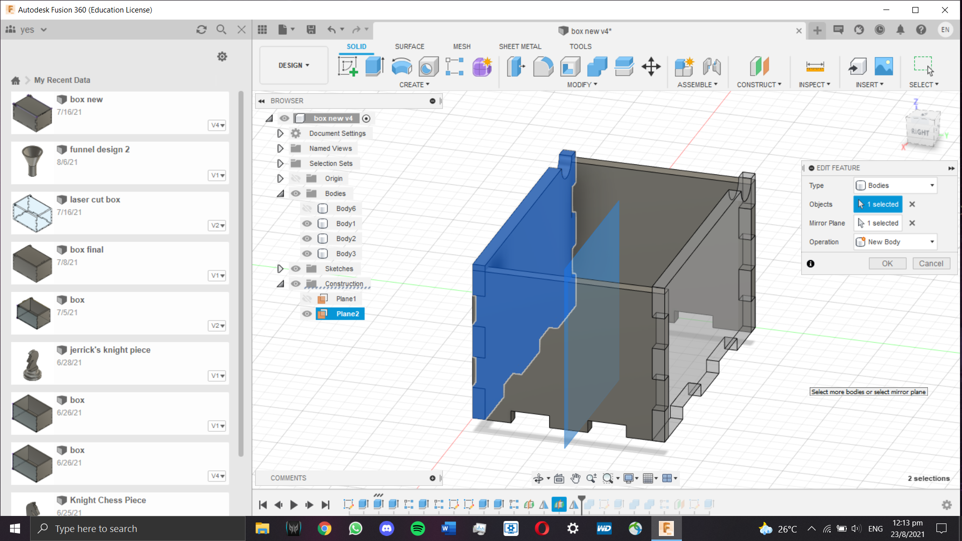
Now that one side of the length and width of the box is done, to make it easier I decided to duplicate both plates by mirroring them.
Before I can do that, I need to create 2 sets of sketching planes at the midpoint of each plate using the midplane tool.
Once the midplanes are formed, each face can be duplicated via the mirror tool.
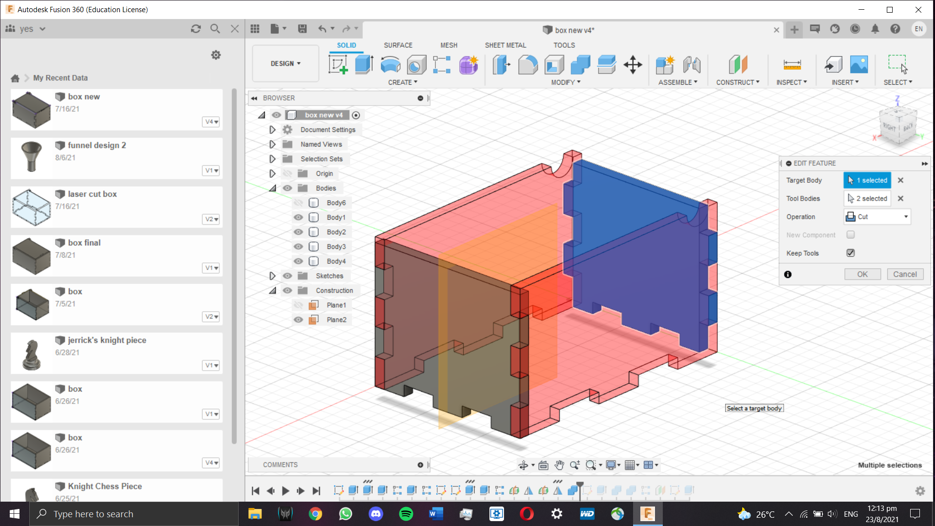
To ensure that the tabs integrate with each other and serve their function, I had to ensure each face does not have parts clipping
into each other. To do that, I used the combine tool. Using one face as the target body and the two perpendicular bodies as the tool
bodies, the 4 faces will not interfere with each other.
)
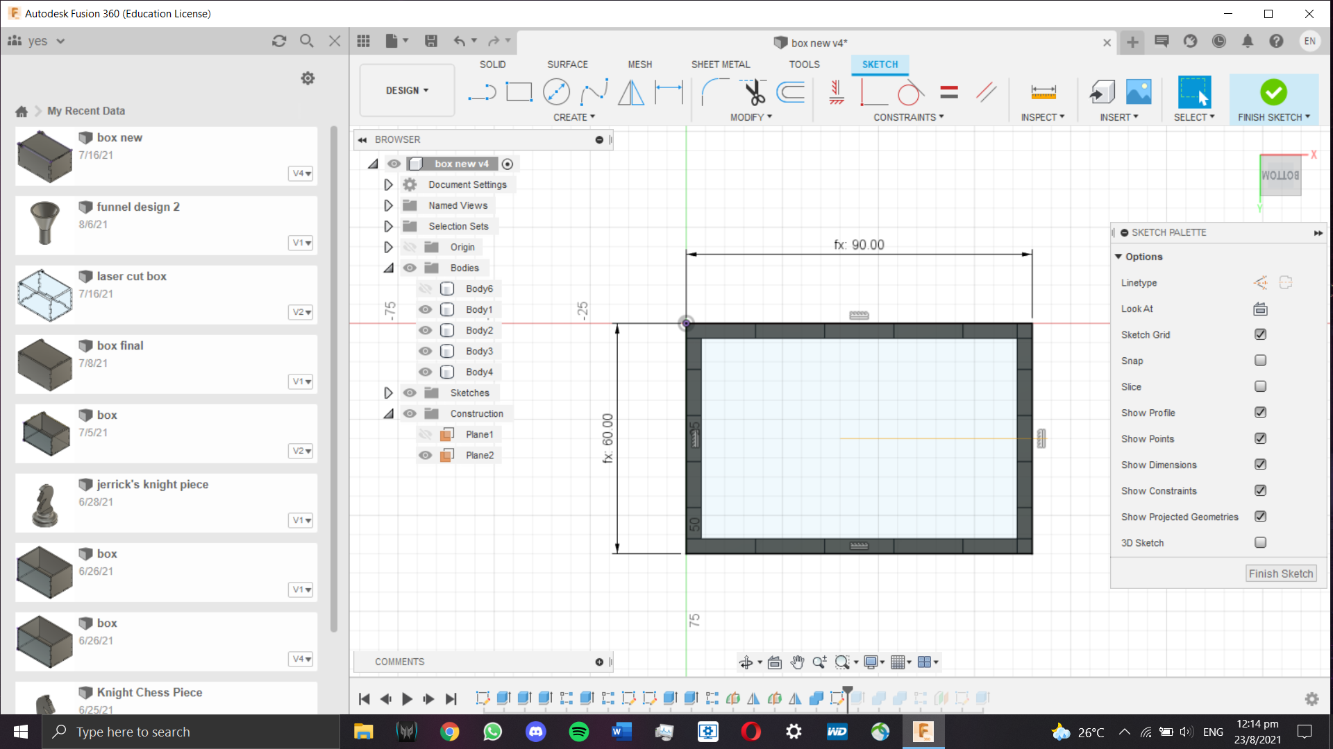
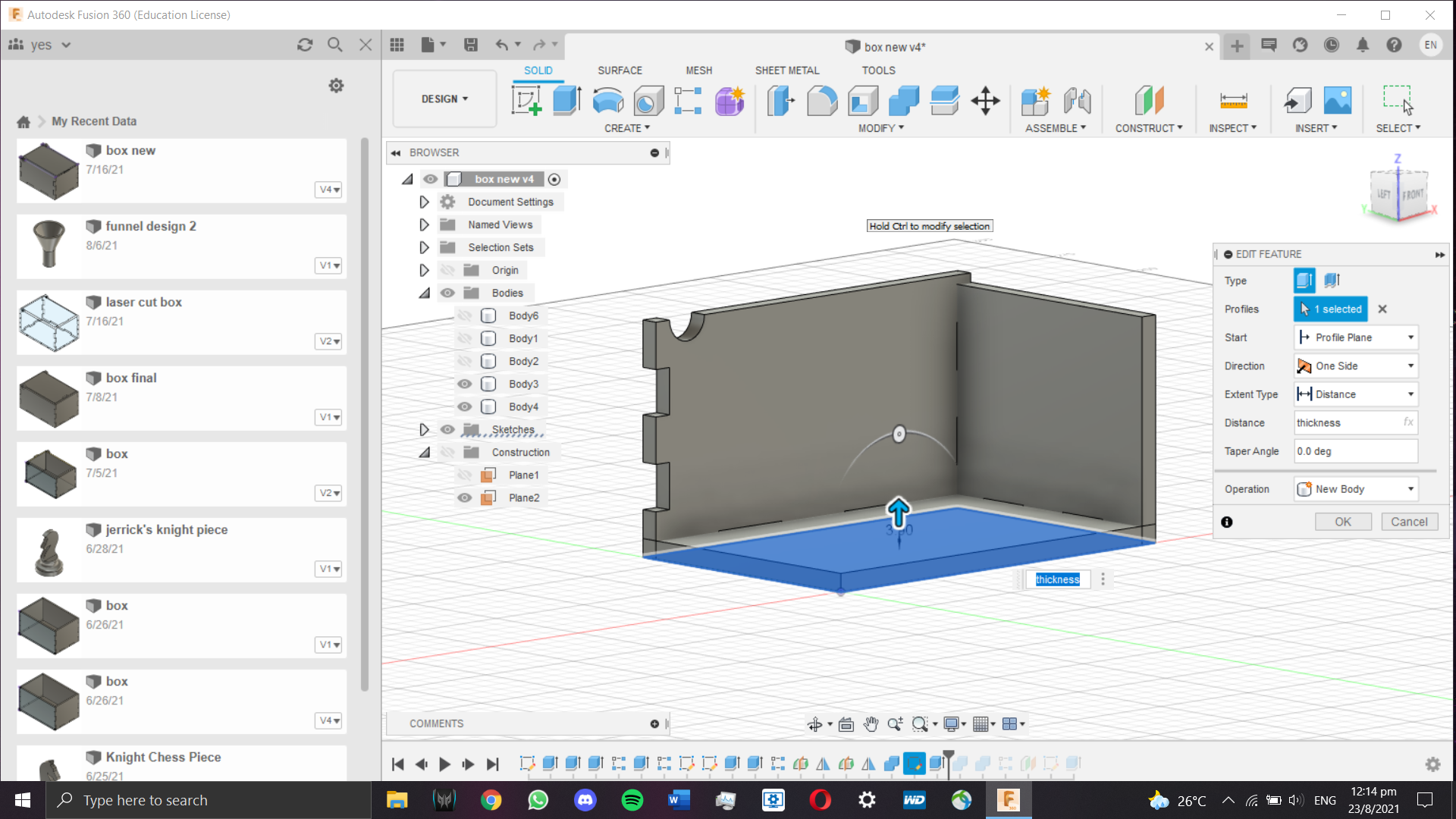
With that out of the way, time for the base. A rectangle was sketched and constrained by the outer side of each face created just now.
It was extruded to our set thickness inwards, intersecting the existing sides.
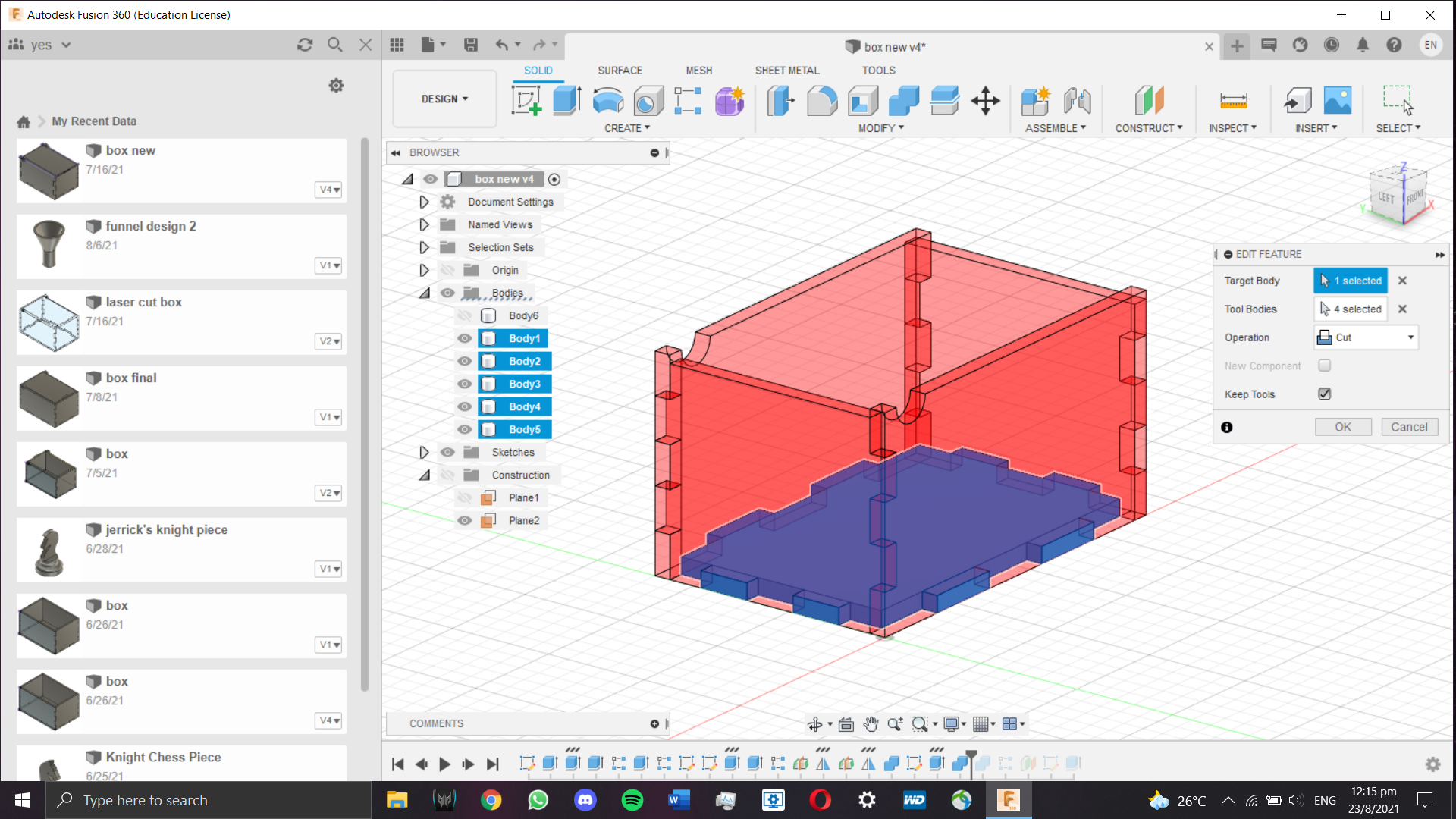
To wrap up the base, the combine tool was used one more time to ensure the base does not have any components clipping into the other
bodies. The 4 sides were selected as tool bodies which were kept after the cut. Now our base of the box is done.
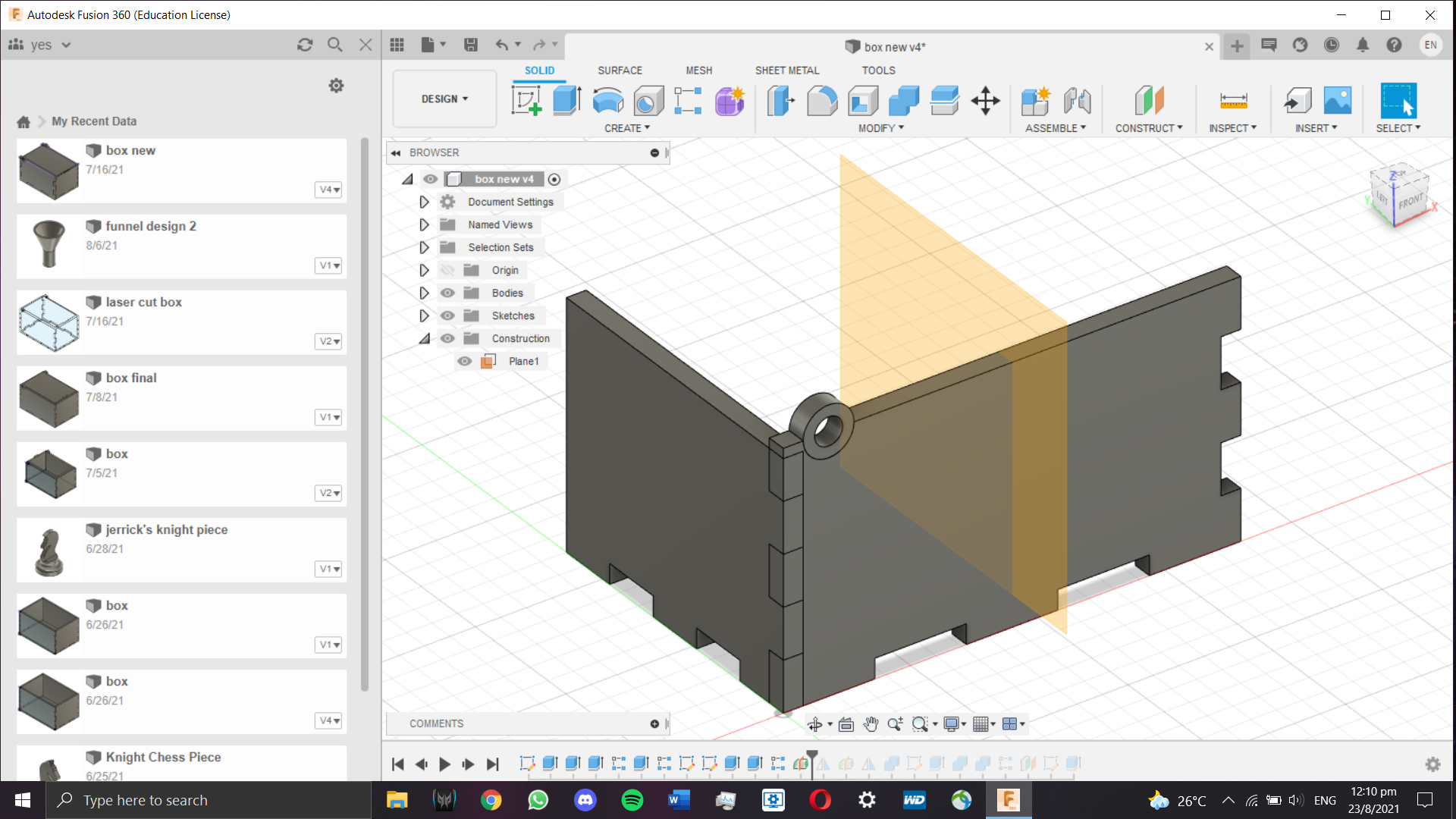
Time for the lid. I decided to make things simple by 3D modelling a hinge that can be laser cut. To start things off, I had to edit
the first sketch I made to include the hole for the hinge to fit.
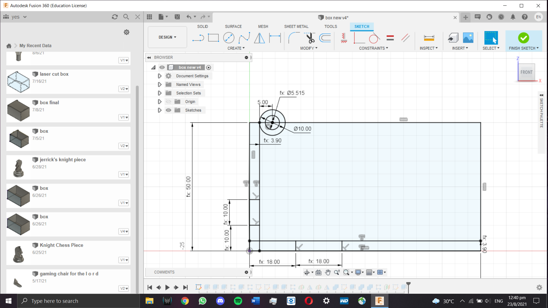
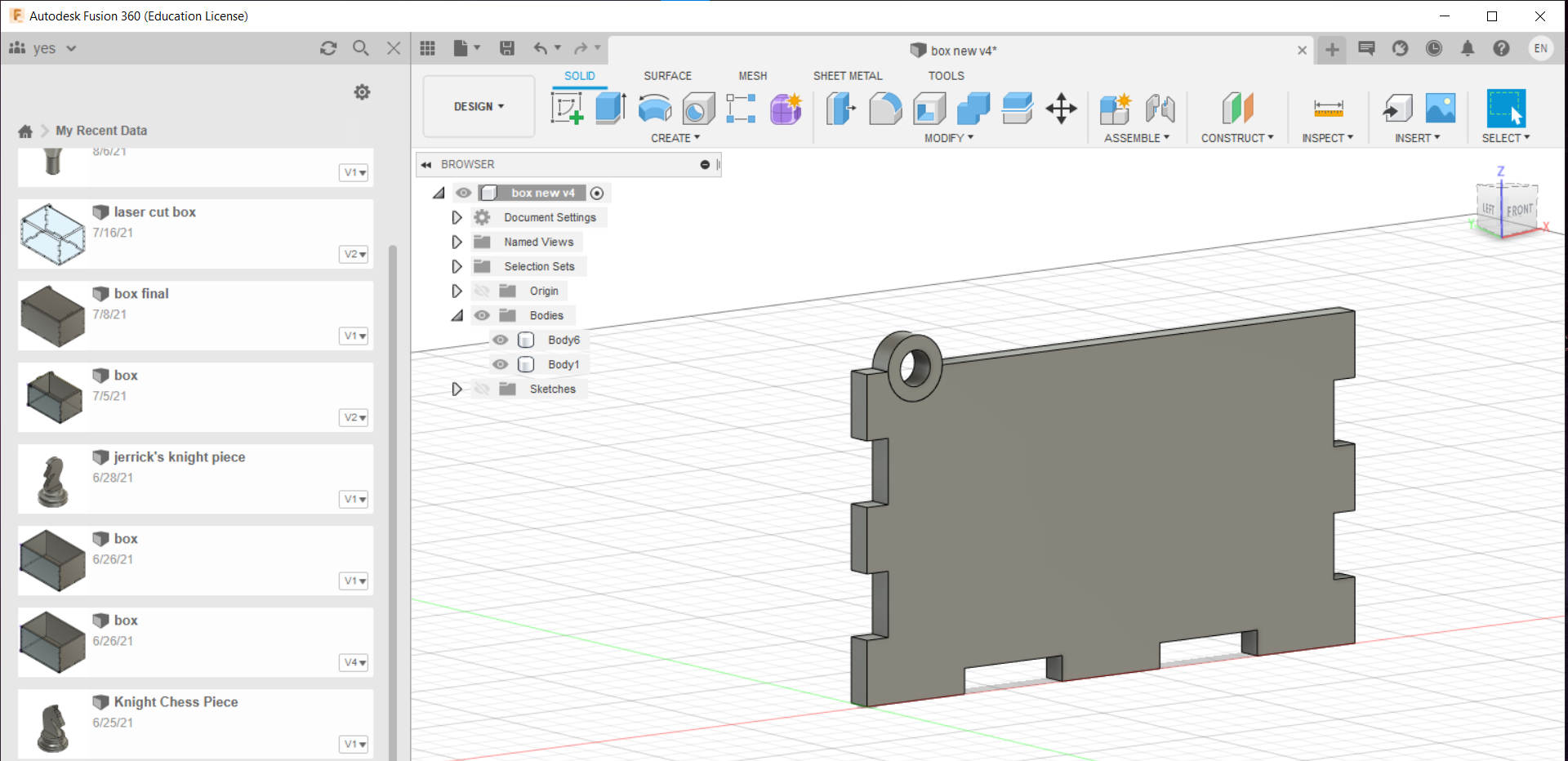
Next, I extruded and patterened the hole since it is needed on both sides.
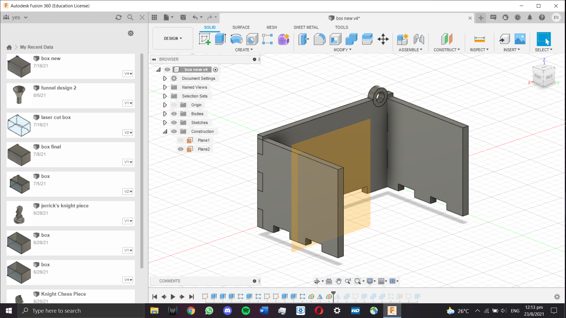
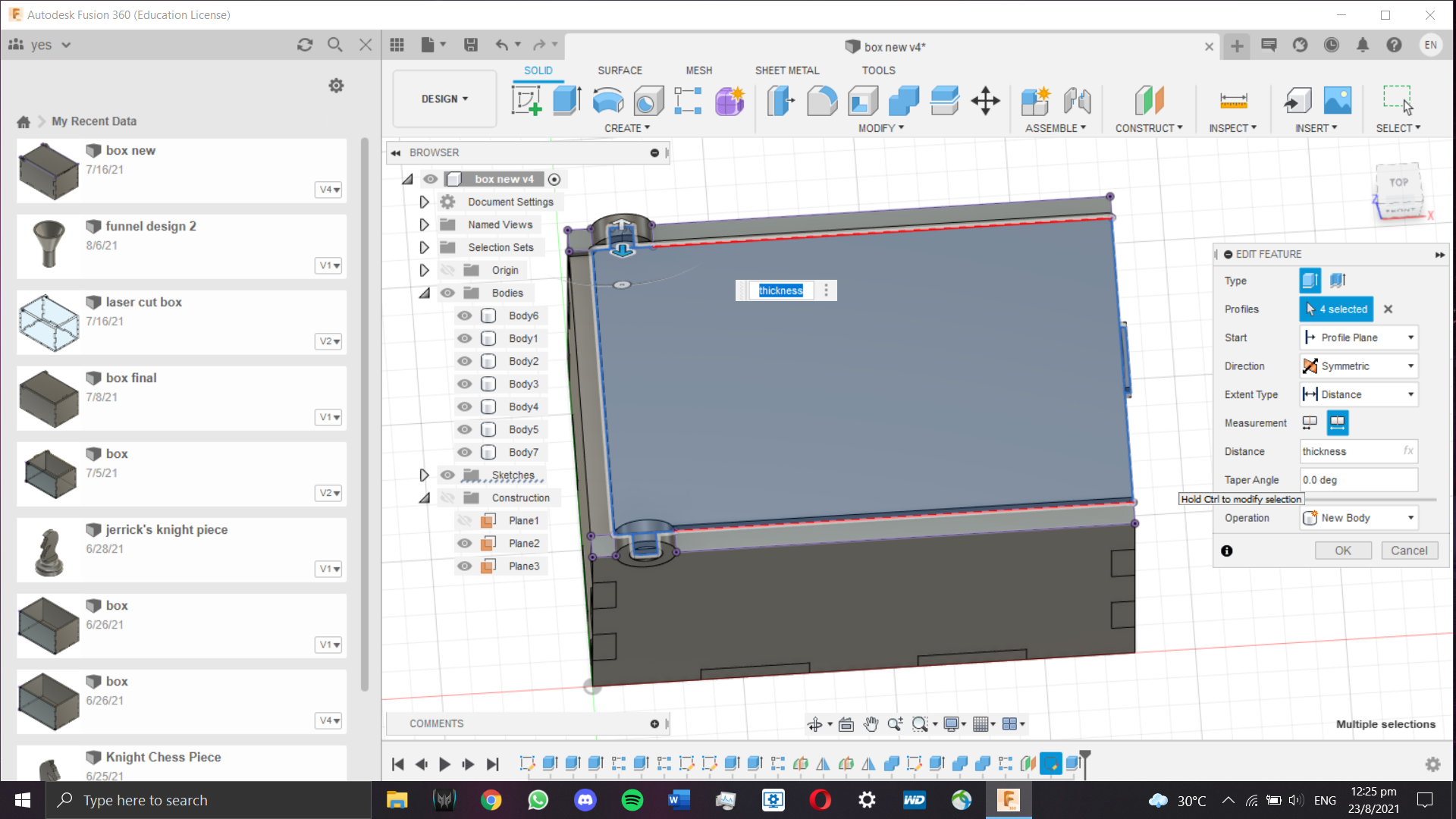
Afterwards, I needed to design the lid. I made a sketch just above the top of the base and sketched a rectangle constrained within
the interior space of the box. In addition, I added two pegs that will be fitted inside the hole, as well as a slight overhang to
make the box openable. Since the pegs are not located at the end of the lid, the excess area needs space in order for the lid to
be openable. This is where the shorter faces come into play.
The lid was then extruded to the preset thickness. With that, the box is done.
Below is the embedded 3D model: